Inverter is a device that converts dc power into ac power at desired output voltage and frequency. The output voltage waveform of an ideal inverter should be sinusoidal. However, the waveform of practical inverter are non sinusoidal and contain certain harmonics. For low and medium power applications, square wave or quasi square wave voltages may be acceptable. For high power applications, low distorted sinusoidal waveform is required.
Types of inverter
According to nature of input source, there are 2 types of inverter
- Voltage source inverter
- Current source inverter
Voltage source inverter has a stiff dc voltage while a current source inverter has a high impedance in series with the dc source.
The output voltage of a VSI is independent of the nature of the load.
Types of voltage source inverter
- Single phase inverter
- Three phase inverter
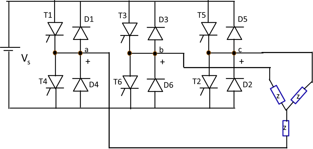
Three-phase full bridge inverter
It consists of six switches and six diodes. Diodes are used to allow bidirectional current in case of non-resistive loads.
The three phase inverter can be operated in two modes to achieve the three phase ac waveform.
Two modes of operation
- 180 degree mode of conduction
- 120 degree mode of conduction
Here we will see about the 180 degree mode of conduction.
In this mode,
Each thyristor conducts for 180°
Three devices conduct at any time
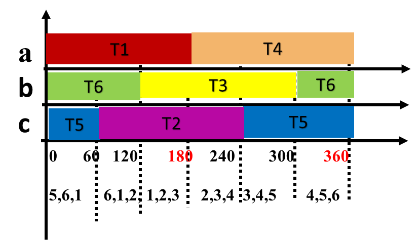
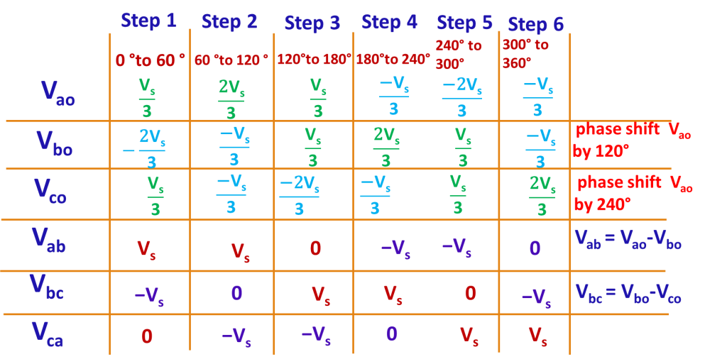
In each step 3 devices conduct. One device from each phase conducts. When two upper devices conduct, the voltage across that phase will be Vs/3 and the third phase in which lower devices conducts will have -2vs/3. Voltage calculation in each step is given in detail in video and is tabulated here.
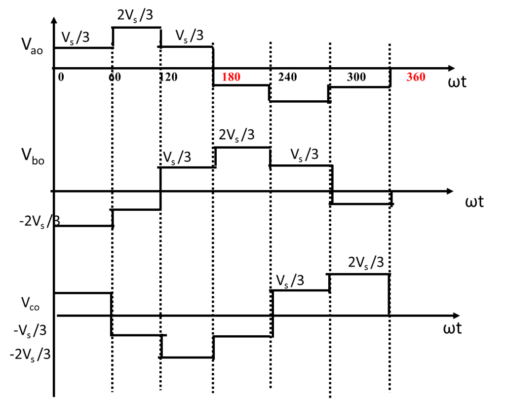
Phase voltage waveform
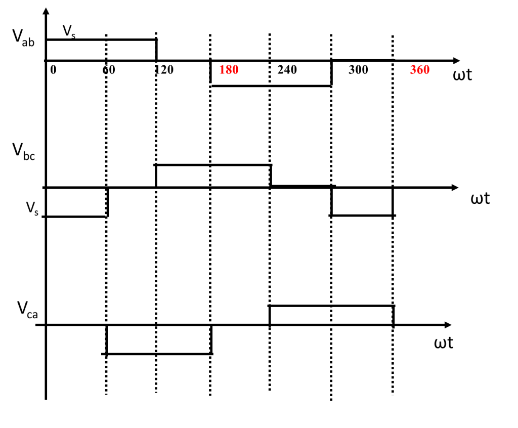
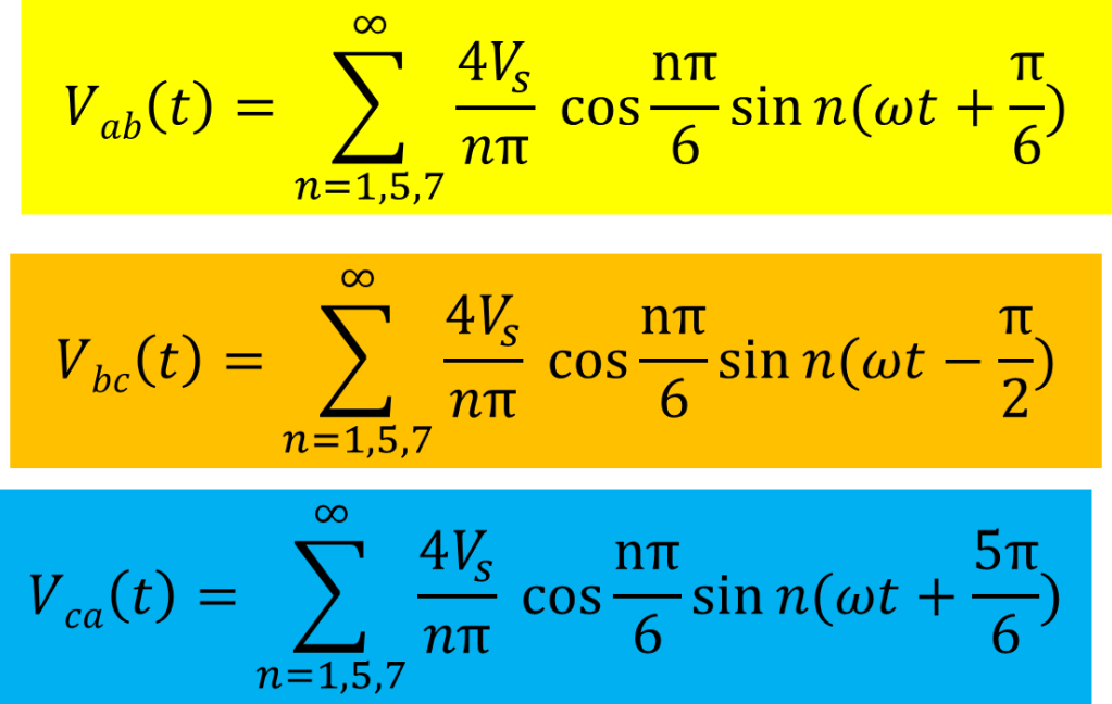
Line voltage waveform
Fourier analysis of output voltage of three phase full bridge inverter
The output voltage of the inverter is a periodic function. We are more concerned about the fundamental component which contributes to useful work. We want to remove the unwanted other harmonic components. Hence a fourier analysis on the output voltage waveform can help to identify the harmonics and eliminate it.
Fourier series is an infinite series used to represent a periodic function.
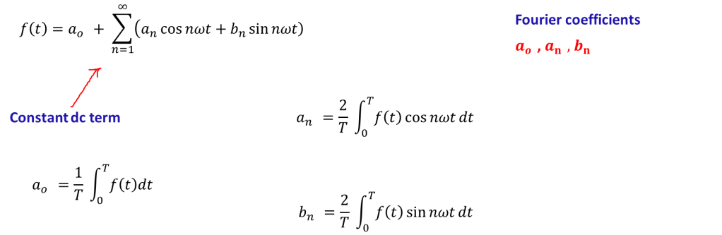
It is not difficult to find the Fourier coefficients if we know the symmetry of inverter output waveform .
Effect of phase voltage waveform symmetry on Fourier coefficient
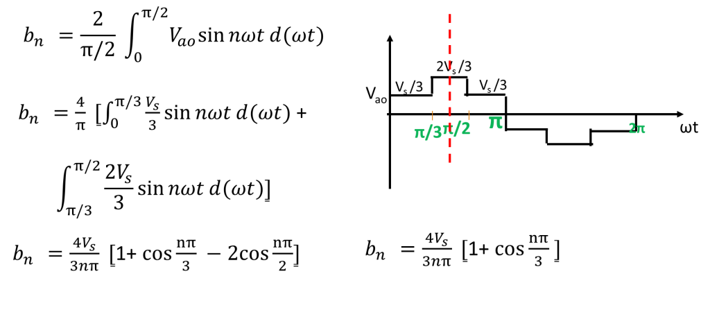
The phase voltage of inverter waveform exhibits odd symmetry and half wave symmetry. In such cases, only odd harmonics exists and coefficients ao and an will be zero.
Let us find triplen harmonics

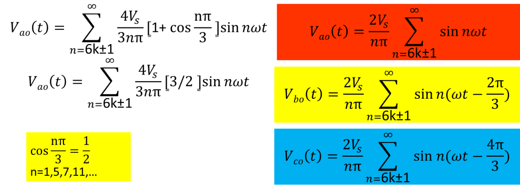
Fourier series for phase voltage waveform
Performance parameters
It is necessary to find the total harmonic distortion in the output voltage waveform. An inverter is desired to produce a sinusoidal waveform, but actually it produces a square wave/quasi square wave output.
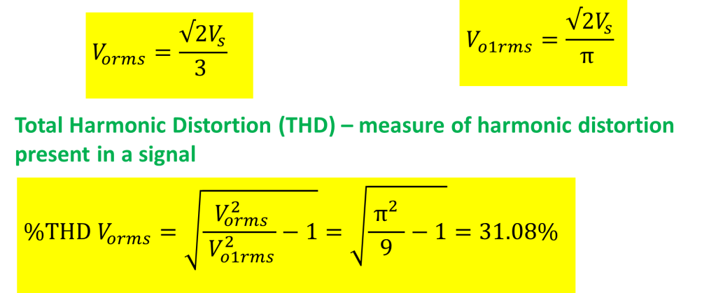
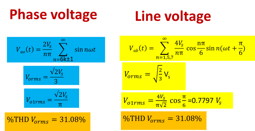
fundamental component-phase voltage

Rms value of phase voltage
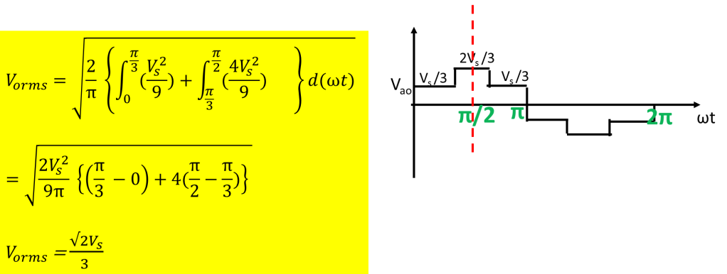
Total harmonic distortion
Effect of line voltage waveform symmetry on Fourier coefficient
The line voltage does not exhibit any symmetry. So we can shift the line voltage waveform by 30 degree so that line voltage waveform exhibits quarter wave symmetry. The voltage Vabs is the phase shifted line voltage waveform which exhibits quarter symmetry. In this case both a0 and an are zero.
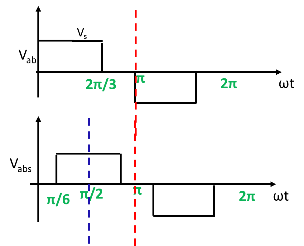
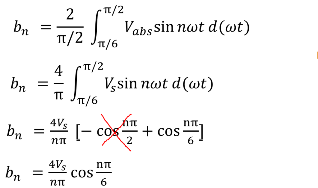
To get the Fourier series for original line waveform, replace wt by wt +30 degree, as we have already shifted the waveform by 30 degree.
Points to remember
- Three phase Inverter converts DC voltage to 3 phase AC voltage.
- In 180° degree mode of conduction
- Each thyristor conducts for 180 °
- 3 thyristors conduct at any time
- Six step inverter
- Output voltage is independent of nature of load
- THD is lower than single phase inverter
